This window provides a series of paged controls for configuring the plot display area. This help section describes each page in turn. Global options that apply to the configuration window as a whole are the ability to Auto-update any changes to what the display area is showing and to save and restore configurations to and from an XML storage system.
Normally configuration changes happen immediately as Auto-update is switched on by default. If you prefer to wait for changes then you will need to press the Draw button. You also need to press the Draw button when making changes to the data limits (these may not be in a valid state until you’ve entered the complete coordinate value).
Accelerator keys
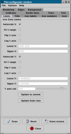
This page allows you to set the physical limits of the axis drawn in the display area. The default configuration auto-scales all spectra to fit within the currently available display area.
If you want to apply limits of your own then, untick the auto-scale checkboxes and enter your values in the lower and upper entry areas. Remember to press Draw to apply the limits.
You can also get either axis to display itself using logarithmic scaling (if possible, there are limitations, like not being able to contain the coordinate zero) and to display the axes ranges flipped top to bottom or left to right.
Other useful options are the checkboxes Fit X range: and Fit Y range: that also make the ranges that you supply fit the visible display area exactly (these are like the fitwidth and fitheight options in the plot window) and Y auto cut: which applies limits to the Y axis using percentile cuts (the data used to estimate the limits lies within the current X coordinate range).
The Update to current button sets the X and Y limits to those of the full plot (these are the values shown initially). The Update from view button sets the X and Y limits to those of the visible part of the display area. This is useful to just show coordinate axes for what you can see.
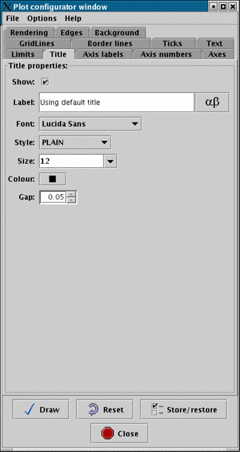
This page allows you to change the title shown in the plot. Using the controls you can define the
font, style, size, colour and gap, from the nearest axis, of the title. You can also decide to
have no title shown and insert any character from the chosen font (depends on the font,
but usually these include the Å sign, press the  button to see the character selection
window).
button to see the character selection
window).
The text shown in the Label: field is an accurate rendering of what is shown in the plot window. The
default title can be restored by setting the text of this field to blank, or to the text Using
default title (this text is used so that you can see the result of any changes you’re about to
make).
Superscript and subscripting are available using AST Escape sequences, for instance:
| AST escape sequence | result |
| super%^100+script%^+ | |
| sub%v100+script%v+ | |
| %% | |
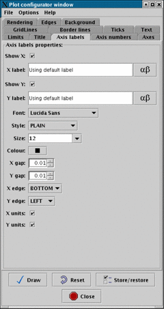
This page allows you to set the labels used on the X and Y axes. It also allows you to choose the font, style, size and colour used, as well as how far to position from the axis, which axis to attach to and whether to include any units (as a string in parenthesis). The text shown is an accurate rendering of what is shown in the plot window.
As with the title you can insert any characters from the font, and use AST Escape sequences to get effects like super and sub-scripting.
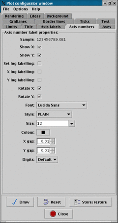
This page allows you to configure how the axis number labels are rendered. As with other pages you can define the font, style, size and colour used, as well as the separation between the actual axes and the labels. An accurate rendering of how the labels will be drawn is shown in the Sample: label.
The Set log labelling: option controls whether the numbers are drawn using an exponent notation. This is the default if log spacing has been selected for the axis (so you can also use this to not get exponent labelling when the axes are drawn using a log scale).
The Digits: drop down box allows you to override the default number of significant figures shown in the labels. Just choose a number that you want. However, note that the number of significant figures is used in the algorithm for determination how to space major ticks, so it may be necessary to increase this value when configuring the major tick separation.
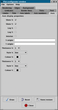
This page allows you to control whether axes lines are drawn around the plot or not. In general this isn’t very useful for spectral plots (when the outer border lines and axes are coincident), but it does allow you to draw the axes inside the display area and position where these are drawn, so you can define an arbitrary origin. Useful effects can then be obtained using grid lines.
The Log X: and Log Y: options are the same as those shown in the Limits pane.
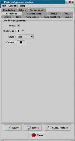
This page allows you to configure if grid lines are drawn in the plot, or not (not by default). Grid lines are drawn between the major ticks. You can also set the thickness, style and colour of the grid lines.
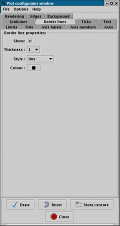
This page allows you to configure if border lines are drawn in the plot, or not. Border lines are drawn at the data limits of the plot. You can also set the thickness, style and colour of the border lines.
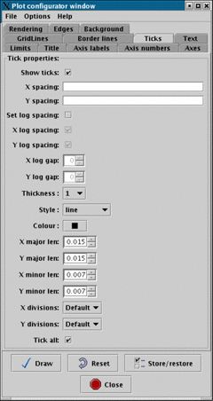
This page allows you to define whether to show major and minor tick marks or not. It also allows you to define the spacing between major ticks and the number of divisions (minor ticks plus one) between major ticks, as well as the properties of the tick lines and their lengths.
The spacing used between major ticks may be dependent of the number of significant figures used in the axis number labels, so you may need to also change that.
The option Set log spacing: together with X log spacing and Y log spacing allow you to define if the spacing of major ticks along an axis are logarithmic. If the axis is scaled logarithmically (that is you’ve asked for log axes in the data limits tab) then log spacing is the default, otherwise major ticks are spaced linearly.
When spacing logarithmically you can define the separation of the major ticks using X log gap: and Y log gap:. These values are the power of 10 you require between adjacent ticks, so for instance, if you wanted ticks every factor of you’d use .
This window has no uses in SPLAT-VO.
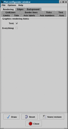
This page allows you to define how carefully the graphics are drawn in the plot display area. By default any text is drawn using anti-aliasing, which makes the graphics less jagged, and spectra are drawn without anti-aliasing. If you’d also like the spectra to be anti-aliased tick Everything:.
It’s not possible to anti-alias the spectra and not the text (so it’s not just a perverse choice of options). Also note that any rendering options are applied to any captured JPEGs produced in the plot.
Finally anti-aliasing is a CPU expensive procedure so it can result in a significant performance degradation (so the default is switched off for spectra).
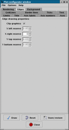
This page allows you to change the amount of space reserved around the plot for displaying titles and axis labels etc.
It also clips any points of any of the plotted spectra that lie outside the bounds of the data limits (this is not normally the case, unless you’ve defined data limits of your own).
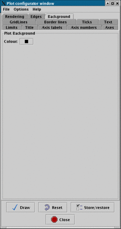
Use this page to select a colour for the background of the plot display area.
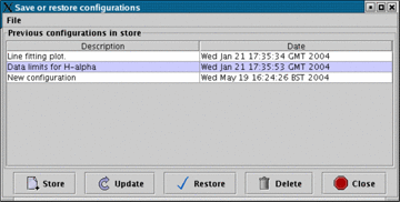
This additional window is activated by the Store/restore button. It’s purpose is to allow you to create a database of configurations that you’d like to keep (after all if you’ve spent some time configuring the look of a plot you don’t want to have to type it all in again when someone asks you to tweak the postscript).
The configurations are identified by two elements, a Description entered by you and the
date when the configuration was created. To create a copy of the current configuration
(note this doesn’t include the spectra themselves) just press the Store button. This creates a
new entry with the description New configuration. To change the description just double
click on this text and type in your changes. Remember to press <Return> when you’re
done. To remove any un-needed configurations select their rows and press the Delete
button.
To restore a configuration just select it and press the Restore button. The actual data is stored in the
file: $HOME/.splat/PlotConfigs.xml. If things seem badly broken then try deleting this
file.